Views of the Radar Sensor Control Box

RSCB Top View

Connectors indentified clockwise from top left:
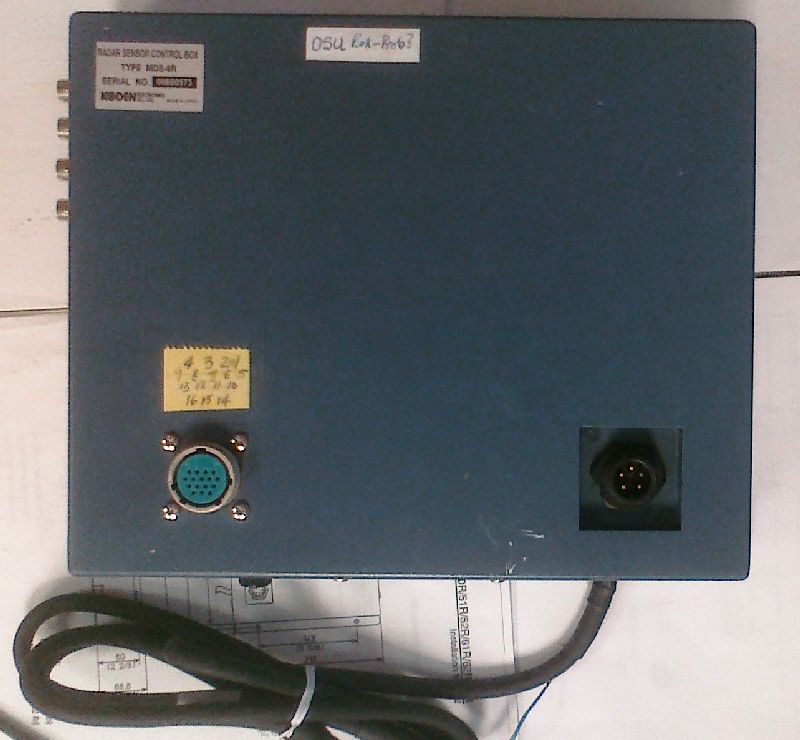
  • BNC connectors from SI-TEX-IF card
  • Power connector (goes to the 28V PS)
  • Connector for cable to T/R unit
RSCB top view

RSCB Front View

On the left is a fuse for the motor power supply. On the right is where the switch cable comes out. At the end of the switch cable are two wires that are twisted together (effectively a closed, always on, switch).
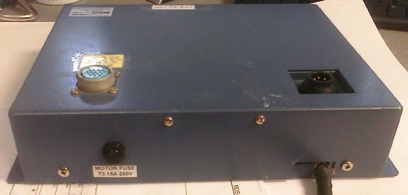
RSCB front view

RSCB Left View

RSCB left view

RSCB Back View

The Ethernet jack. This is what is susceptible to coming loose, even when the plug is "clicked in" to the jack.
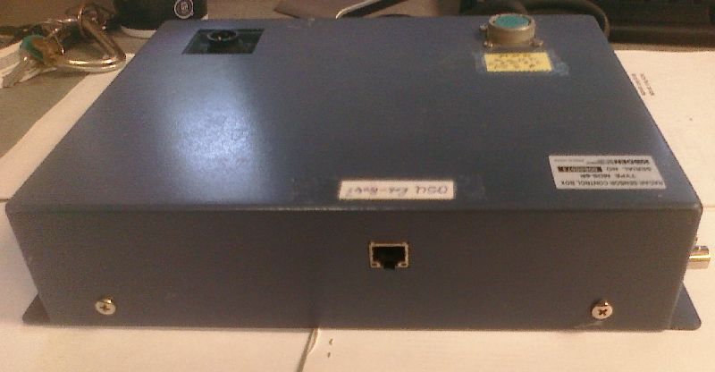
RSCB back view

RSCB Inside View

Note the power/control board cable usually is connected to the top of the SI-TEX-IF board, but is disconnected in this picture. Also, the switch cable is removed in this picture.
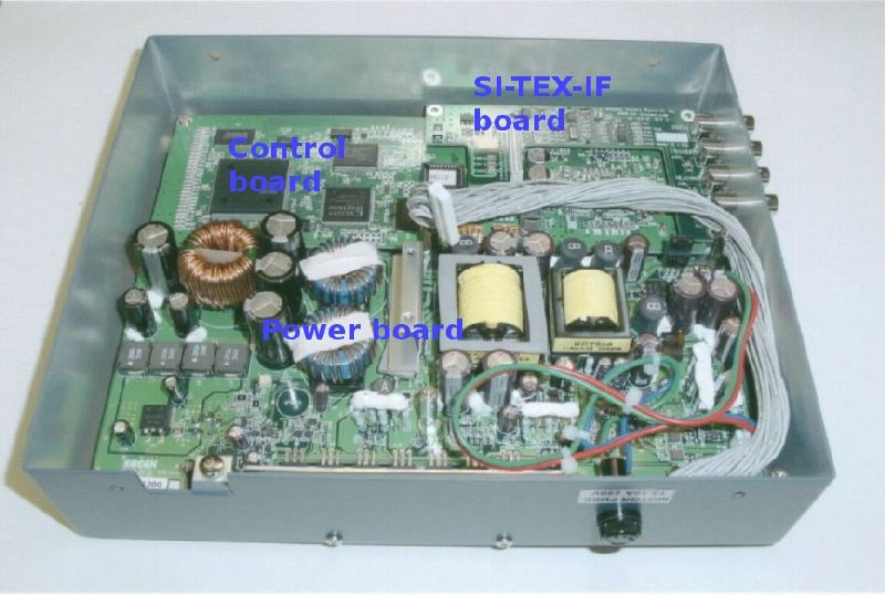
RSCB inside view

RSCB Inside View with SI-TEX-IF card removed

Note the DIP switches are only visible when the SI-TEX-IF card is removed. These are the switches used for setting the box's IP address.

The SI-TEX-IF card's bottom cable would connect to the empty header, were it installed.

RSCB inside view with SI-TEX-IF card removed

The SI-TEX-IF card

The SI-TEX-IF  card

Parts of the DAQ PC

The QuadRec Card

The ISR QuadRec card on a table

QuadRec Connections

Note that

Connections to the QuadRec card