Contents (hide)
- 1. What is Radar?
- 2. How does radar work?
- 2.1 Pulse Radar
- 2.2 Range
- 2.3 Azimuth
- 3. How do we record radar data?
- 3.1 Radar Signals
- 3.2 Video Digitization
- 3.3 Azimuth Determination
Note: Detailed and scholarly explanations of using radar for ocean wave detection may be found in the articles located on the share at Radar_System_Info/Journal Articles/. There also are a series of excellent tutorials at radartutorial.eu. This page is intended as a simple primer.
1. What is Radar?
RADAR is an acronym that that stands for RAdio Detection And Ranging. Simply stated, it is a method for using radio waves to locate objects.
2. How does radar work?
2.1 Pulse Radar

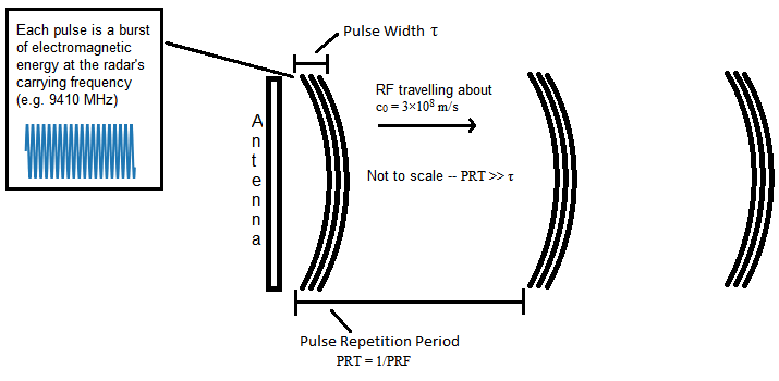
X-band marine radar is a "pulsed" type of radar. The radar emits of a pulse of RF energy at a constant rate (the Pulse Repetition Frequency, or PRF). The pulse length τ is also constant. Objects are detected by measuring the pulse signal as it reflects off these objects.
2.2 Range
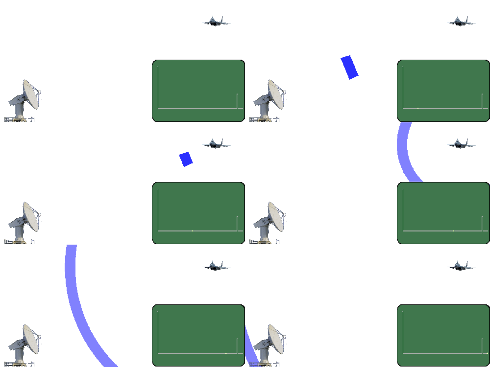
Range detection

Retrieved from http://www.radartutorial.eu/01.basics/Distance-determination.en.html
A radar can find out how far away an object is by transmitting a burst of energy (pulse) and then timing how long it takes for that energy to travel out, bounce (scatter or backscatter) off the object, and travel back to the radar's receiver.
Radio waves travel at the speed of light c0—about 3 x 10⁸ m/s.1 Thus the time T it takes for the radar pulse to travel the distance d to the target and return to the radar may be represented as:
{$$ T = \frac{2d}{c} $$}
Thus, if it takes T seconds to receive the backscattered signal, the distance to the scatterer is:
{$$ d = \frac{Tc_0}{2} $$}
So if T = 1 Ás, then the scatterer is about 150m away.
A few details:
- There are likely multiple scatterers in the path of the transmitted pulse at different ranges. Since the radar listens for "echos" from the time the pulse is transmitted until the next pulse is transmitted (roughly), it can hear multiple returned signals from different ranges.
- Different objects reflect different proportions of the transmitted signal. Radar sytems generally record not only the time it took to receive the transmitted pulse, but also the intensity of the received pulse.
Range Discrimination
The radar's pulse has a duration; that is, it is not infinitesimally short. In effect, this means that the radar does not have infinitely high resolution in the range--if two targets are close together in the range axis they will "smear" together. The radar's range discrimination Sr may be related to the radar pulse length τ as:
{$$ S_r \ge \frac{c_0\tau}{2} $$}
For example, a radar operating with a pulse length of τ = 0.08 µs will have aminimum analog range discrimination Sr of about 12 m.
Range Limits
Minimum Range
The radar cannot listen for returns when it is transmitting, both for logical and technical reasons (there is only one antenna, so there has to be a switch for receiving or transmitting). Thus the minimum range of the radar is limited by the pulse length τ and any time the radar needs to recover after the transmission before it can start recieving, trecovery. Thus the minimum range of the radar may be expressed as
{$$ \rho_{min} = \frac{c_0(\tau + t_{recovery})}{2} $$}
Note that trecovery may need to be determined empirically. In the ideal case where trecovery ≈ 0 and using our τ = 0.08 µs, we get ρmin ≈ 12 m.
Maximum Range
We know:
- The radar transmits RF pulses continuously (at some duty cycle determined by the PRT and pulse length) as it rotates, to detect objects at different azimuthal locations and to update the positions of objects in time.
- The radar cannot listen for pulse returns (backscattered energy) while it is transmitting.
- Once the radar has transmitted a new pulse, any returns from previous pulses are invalid.
Thus we can say that the radar has a certain maximum "unambiguous" range that is determined by the delay between radar pulses. This is expressed in the equation
{$$ \rho_{max} = \frac{c_0 (PRT - \tau)}{2}$$}
Where PRT is the pulse repetition time (or period), or the inverse of what is known as the pulse repetition frequency, or PRF. For example, a radar operating with a nominal PRF of 2000 Hz will have a PRT of 5 µs, which gives a maximum unambiguous range ρmax of ~75 km.
You may ask, "Why the qualifier, 'unambiguous'?" Well, even though we would consider signal reflections from a previous pulse to be invalid, the radar doesn't know that! As far as the radar is concerned, those returns may be from the most recently transmitted pulse. However, as I noted above that the PRF of a radar is a nominal value (e.g. 2000 Hz). In actuality the PRF is likely dithered by roughly ▒5%. This means that out-of-range (or ambiguous) returns will not show up at the same range for successive pulses. This allows these returns to be filtered or averaged-out by the radar processing/display system.
Slant vs Ground Range
It is important to remember that the radar system reports line-of-sight distances to scatterers. Thus, if a radar is operating at elevation h above an ocean surface, an object located at range ds is at ground range {$ d_{g} = \sqrt{d_{s}^{2} - h^{2}}$}. Of course any objects closer than h have a ground range of 0. Diagram and details at Wikipedia: https://en.wikipedia.org/wiki/Slant_range.
2.3 Azimuth
Azimuth Detection
A standard X-band marine radar spins at a near-constant rate. However, friction and wind effects modulate the radar's rotation rate so that it is not a reliably accurate indication of the radar's azimuthal position. For this reason, the radar's angular position is determined by an encoder that outputs Azimuth Change Pulses (ACPs) at fixed angles as the radar rotates. For example, if the radar outputs 4096 ACPs per rotation, the difference in angle between each ACP is 360/4096 ≈ 0.88°/ACP. This would thus be the raw precision of the radar azimuth angle.* When the radar reaches 0°, an additional pulse (Azimuth Reference Pulse, North Reference Pulse or heading pulse) is output, which instructs whatever device is counting the the ACPs to restart from zero. The azimuth angle of a given radar pulse is thusly determined by checking the ACP count at the time the pulse is received. On a ship the ship's compass reading must of course also be factored in to determine the true azimuth angles of the radar pulses.
* The raw azimuth resolution may be improved with interpolation by assuming a constant rotation rate between consecutive ACPs.
Azimuth Resolution
A radar with a PRF of about 2000 Hz and a rotation rate is about 40-48 RPM would have a rotational pulse rate of:
{$$ 2000\frac{pulse}{s}\cdot\frac{60\frac{s}{min}}{\le48\frac{rot}{min}} \ge 2500 \frac{pulse}{rot} $$}
If we then divide this into 360 °/rot, we get an azimuthal resolution of about 0.144 °/pulse. But the dithering of the PRF and frictional effects to the rotation rate make this only a rough approximation, and not useful for accurately locating targets. We must count the azimuth pulses.
The horizontal beam width of the antenna places a fixed limit on the possible azimuthal resolution. The page discusses antenna beam width in detail. Antenna Characteristics
3. How do we record radar data?
3.1 Radar Signals
To digitally record radar signals and know the azimuth angle for each radar pulse, we need four signals from the radar:
- Trigger - Rectangular pulses that each signify that the radar is transmitting an RF pulse.
- Video - Demodulated radar signal. The actual radar signal for an X-band radar is a radio wave in the GHz band--this is just the relative intensity of the returned signal as a DC voltage.
- Azimuth or Azimuth Change Pulses - Rectangular pulses output by the radar's azimuth encoder. See above.
- Heading or North Reference Pulse - A single rectangular pulse output each time the radar rotates past its 0° point. Should be in sync with one of the ACP pulses.
3.2 Video Digitization
Somehow, we would like to convert the signal returned to the radar into something we can process with a computer. The method we use to do this is called digitization, i.e. electrically measuring the signal and converting it to a discrete numeric form.
An analog-to-digital converter (ADC) works by measuring an analog electrical signal at a regular frequency. Each measurement is called a 'sample'. For example, in an ADC with a 50 MHz sampling rate, the signal amplitude is recorded every 20 ns. If the ADC has 8 bits of resolution, then the amplitude of each sample may be recorded as a value between 0 and 255 (or -128 and 127, or whatever).2
In the case of our radar, we set up an ADC to listen for a pulse on the Trigger output from the radar. This signifies that the radar is transmitting an RF pulse. The ADC briefly waits (so as not to record any leakage from the initial transmission), and then begins sampling the signal on the Video output from the radar--this is the demodulated received RF signal. We set up the ADC to record a set number of samples after each trigger (e.g. 2048).
Since each sample is a measurement in time of the received radar signal, and we know from the above discussion on range detection that the time at which signals are received can be used to measure distance of scatterers, we can then say that each sample interval represents a given distance away from the radar; the distance of each sample is determined by the sample rate. The digital range resolution of the radar is
{$$ d\rho_D = \frac{c_0}{2f_s} $$}
where fs is the sampling frequency. So for a 50 MHz ADC, (such as exists in our system) the digital range resolution is ~3m. Thus, for 2048 samples, we sample out to a maximum range of ~6144 m.
One may notice that the digital range resolution is multiple times higher than the minimum range discrimination. This is good since the sampling theorem basically states that we should should sample at at least twice the resolution of the highest-resolution features we would like to capture.
3.3 Azimuth Determination
The data acquisition system must count the ACPs, restarting from zero at each heading-zero pulse. Each time and RF pulse is transmitted by the radar (each time there is a pulse on the Trigger output), the data acquisition system should record the value of the azimuth counter, as well as the time of each pulse (e.g. system timestamp). In post-processing, the azimuth counter may be converted to azimuth angle, based on the number of azimuth counts per rotation (e.g. 4096), and then converted to angle from True North by adjusting to the radar's orientation (ship heading, etc.)
1 In the field of Physical Oceanography c denotes water wave speed, so c0 is used for the speed of light ⇑
2 It's up to the circuitry between the source and the ADC to scale and/or offset the signal to be within the range that the ADC expects. ⇑
Select a page group name to see sub-pages.
- Home
- Radar
- Software
- Inventory
- Technical Guides (scripting, linux tools)
- Cape Disappointment
- Newport
- Logs
- Wave Energy
- Processing
- Development
- HPx Radar Server
- WIMR PC Setup
- Field Experiments
- Reports and Investigations
- Trailers
- Public
Sandbox for playing around with markup syntax, etc.
This wiki installation is running PmWiki pmwiki-2.3.21, version number 2003021.
