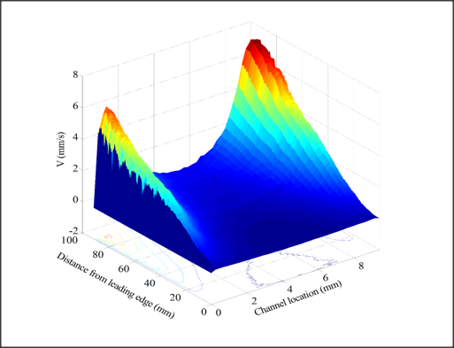
The Bubble Investigation Loop (BIL) facility is a flow loop designed to allow particle image velocimetry measurements to be take on the flow around bubbles. Particle image velocimetry (PIV) is a method of analyzing a flows velocity field by seeding it with micron size particles. The particles are selected, by size and density, such that they are Stokesian in their behavior and, therefore, follow the path of the fluid closely. A laser sheet is passed though the fluid perpendicular to a high speed camera. The light produced by the laser illuminates the seed particles allowing their position to be captured. The images captured by the camera can be analyzed to determine the velocity field inside the field of view. This is done by measuring the statistical change in the position of a small group of particles from one frame to another through a correlation calculation. Measurement of the velocity field provides the raw data for the computation of material derivative and viscous term in the Navier-Stokes equations, creating an expression for the pressure gradient. This expression can then be integrated allowing for determination of the corresponding pressure field. The specific objectives of the data produced by the BIL facility are a reevaluation of bubble drag and virtual mass coefficients as well as an investigation into the physics which govern larger bubble geometries.
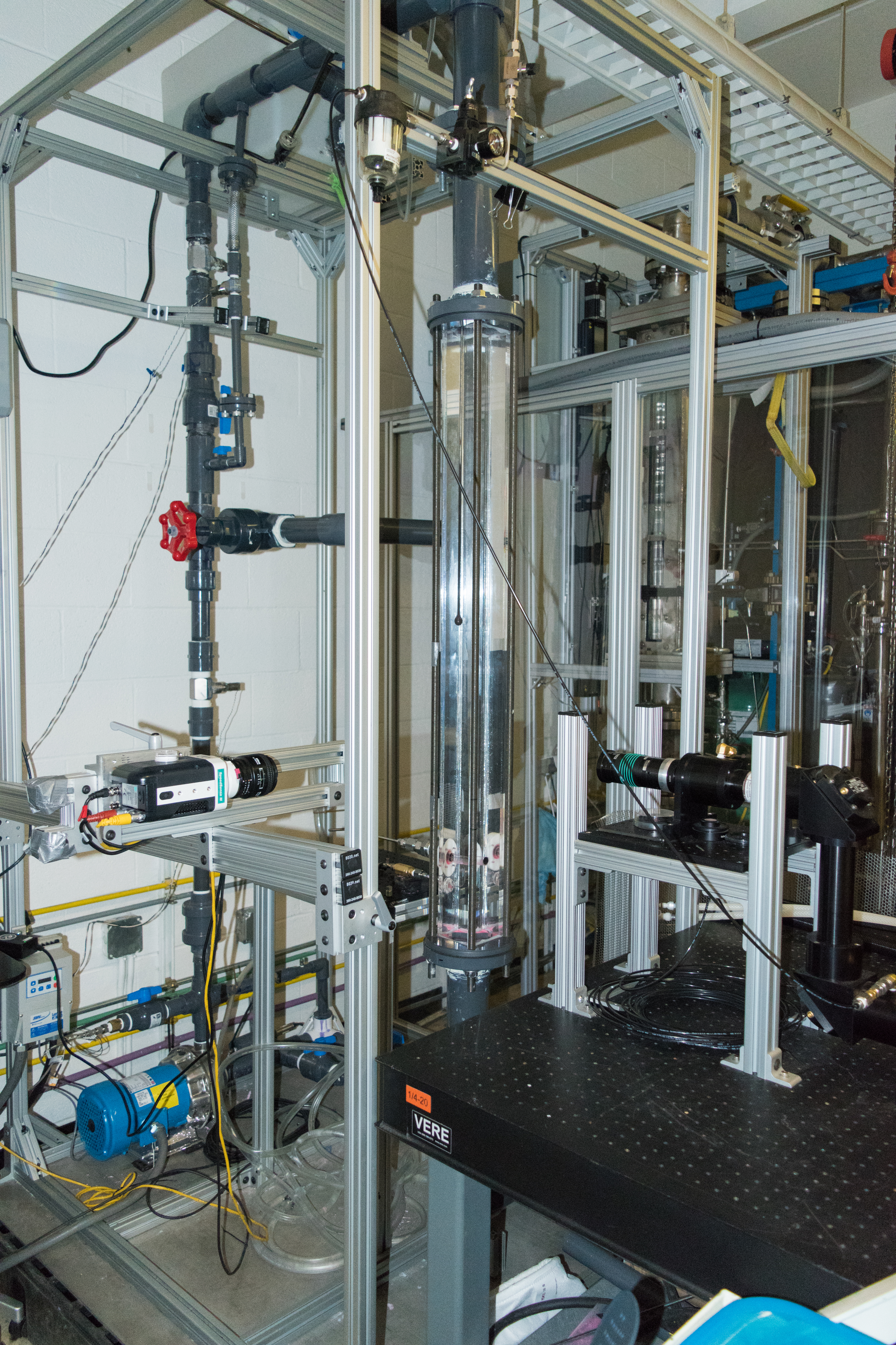
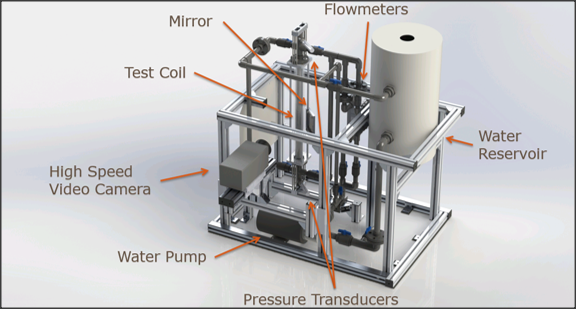
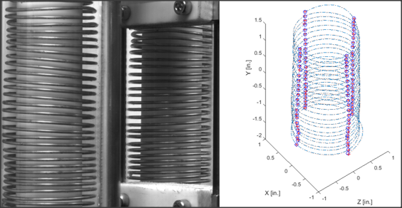
The Camera-Observed and Instrumented Loop (COIL) Facility uses a high speed camera and pressure transducers to analyze cross-flow induced vibrations of a test element over a range of flow regimes. A clear glass cylinder allows for visual access to the element under analysis and an angled mirror provides a simultaneous second view for three-dimensional reconstruction. The initial test element is an aluminum wire wound into a helical coil and attached to an inner cylinder. Piping connects the test section to a fluid reservoir with flow provided by a circulating pump. Flow control meters provide manual control of flow rate. Pressure transducers, before and after the test section, meter gauge and differential pressure across the helical coil.
The purpose of this facility is to fully characterize the motion of a helical coil over a range of flow rates. This will provide insight into how steady flow affects flexible structural elements under similar conditions. A similar geometry is found in current integral Pressurized Water Reactor (iPWR) steam generators. It will also provide empirical data on the pressure drop across a coil under fluid flow when suspended in an annulus.
Flow in this facility has a range between 0.4 and 14 gpm with a fine adjustment resolution of 0.2 gpm. Internal gauge pressure in the test section varies based on the flow conditions, ranging from 0.0 to 12 psig. Pressure drop across the test section can be detected with 0.015 psig accuracy. Adjustment of camera placement gives a range of pixel resolution, from 0.002 to 0.006 inches per pixel.
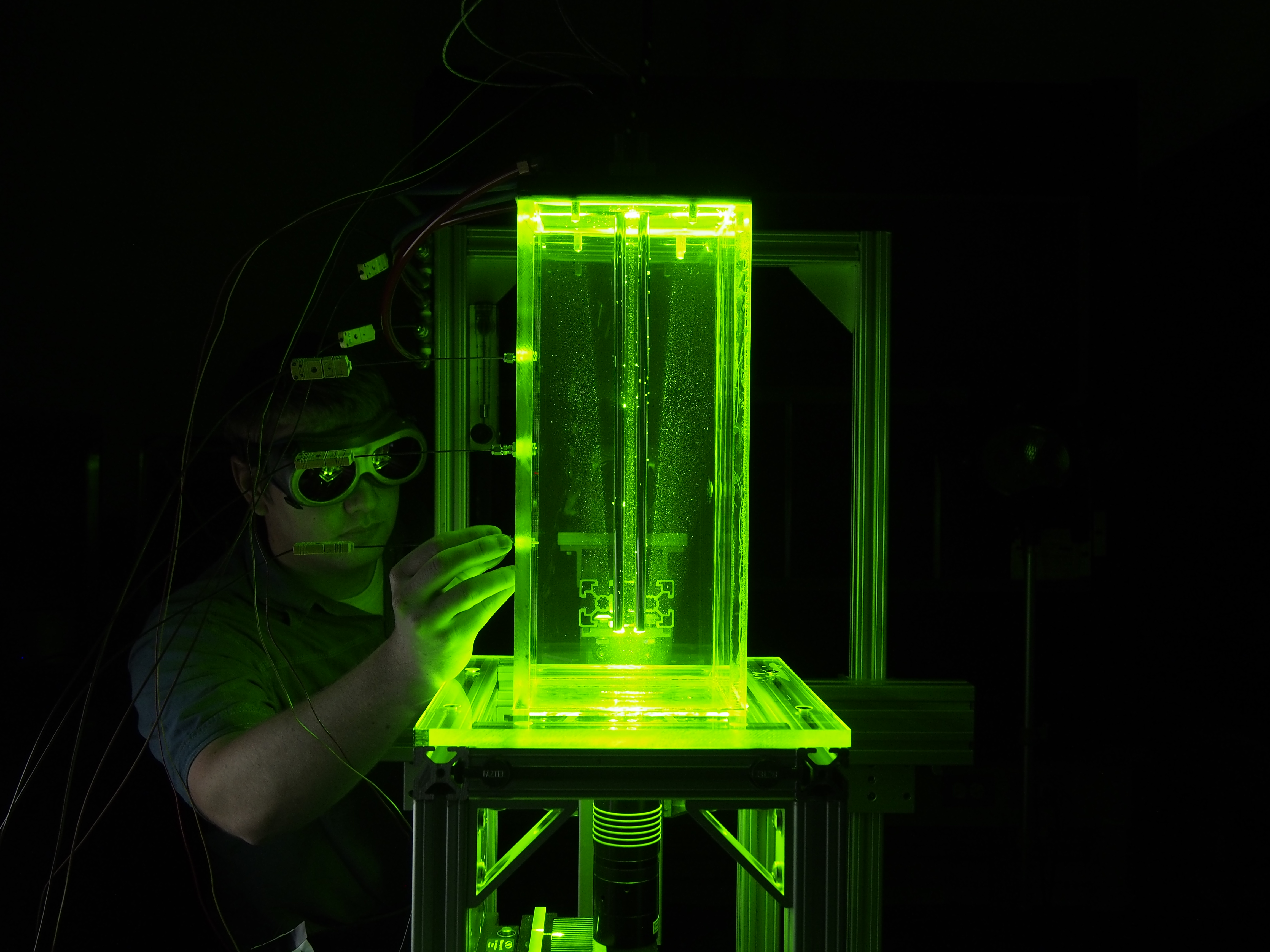
The Laser-Imaged Natural Circulation (LINC) facility is an experimental apparatus designed for the observation of natural circulation phenomena associated with vertical, heated cylinders. Continuous operation of natural circulation flow is made possible by a cooling plate that makes up the top of an acrylic tank, designed to allow heater rods to pass through in configurations that include two 3/8” rods with variable pitch or one rod with variable diameter. It leverages Particle Image Velocimetry (PIV) as well as an array of thermocouples to measure heat transfer and time-resolved fluid velocity. From these measurements, deductions can be made about boundary layer thickness, heat transfer rate, boundary layer transition location, time-resolved velocity profiles and more.
The purpose of the LINC facility is to provide valuable data in support of furthering understanding natural convection in this geometry. It is of particular interest to the nuclear engineering field as the majority of nuclear fuel in use in the world consists of long, slender cylinders which are immersed in water and cooled via natural convection for much of its life. The data acquired from the LINC facility can be applied directly to safety and performance assessment models used to maintain nuclear fuel at safe temperatures at all times.
The LINC facility allows for investigations using two rod configurations with variable pitch as well as one-rod configurations with variable rod diameter. The maximum power that can be supplied to each rod (and removed by the cooling plate) is 1,400 W, powered by a digital power supply with feedback of actual power used. Velocity field data can be collected using the PIV system at frequencies of 5,000 Hz. Temperature is monitored at many locations including inside the tank, internal to the heater rod(s) and at the inlet and outlet of the cooling plate. The chiller that circulates coolant through the cooling plate has a rating of 1,700 W at 20°C. The tank operates at atmospheric pressure.
