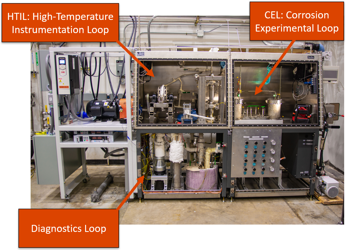
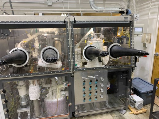
The Glovebox for Experimental Liquid Sodium (GELS) facility is a combined thermal hydraulic and materials test facility that has been co-developed with the Marcum Research Group. The facility is comprised of three separate independent sodium loops: the Diagnostics Loop, the High-Temperature Instrumentation Loop (HTIL), and the Corrosion Experimental Loop (CEL). GELS enables testing in both static and flowing, chemistry-controlled liquid sodium environments at temperatures up to 550°C.
The primary purpose of the Diagnostics Loop is to control the concentration of impurities, and primarily oxygen, in the primary sodium reservoir. It is driven by a DC conduction pump and pushes sodium through a cold trap and a plugging meter, which are plumbed in parallel. Both the cold trap and plugging meter take advantage of the limited solubility of oxygen in sodium at low temperatures to remove and measure oxygen impurities, respectively. Sodium is cooled to precipitate oxygen (as Na2O) and flowed through the cold trap, which is filled with steel wool to mechanically filter out these solid oxide precipitates. The plugging meter consists of a restricted flow orifice that allows for correlation of a drop in flow rate due to oxide precipitate to the saturation concentration of oxygen in the sodium at a certain temperature as it is cooled.
The High-Temperature Instrumentation Loop is a flowing test facility driven by a moving magnet pump. It is capable of forcing liquid sodium flow at temperatures up to 550°C through the test section at a rate of up to 20 gpm, which approaches flow velocities typical of those found in the cores of contemporary sodium fast reactor (SFR) designs. It can be used for testing of in-pile instrumentation in high flow rate sodium environments, or for long-term isothermal erosion corrosion tests for SFR in-core structural materials.
Finally, the Corrosion Experimental Loop is a quasi-static sodium immersion test facility designed for testing of impurity-driven corrosion and liquid metal embrittlement in prototypical SFR environments. Designed for testing at temperatures of up to 550°C, these two parallel flow, independent test crucibles enable flexible experimental design through the use of interchangable lid designs with various feedthroughs. This enables both standard corrosion coupon testing, in addition to both statically and dynamically loaded tests for investigation environmentally assisted cracking via specialized experimental test rigs. A low flow rate of approximately 1 gph is maintained during these tests to provide continuous sodium chemistry-control using the Diagnostics Loop.
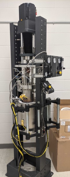
The Molten Salt Load Frame (MSLF) mates a dual-chamber autoclave and an Interactive Instruments Model 5K Servo to enable mechanical testing of materials with simultaneous exposure to molten salt environments. the MSLF is capable of achieving temperatures of up to 700°C through the use of an external, three heat zone clamshell furnace. Salt circulation between upper and lower chambers, which can be held at different temperatures, is achieved through the use of a bubble pump, allowing for simulation of thermal-gradient driven mass transport behavior expected in full-scale molten salt reactor designs.
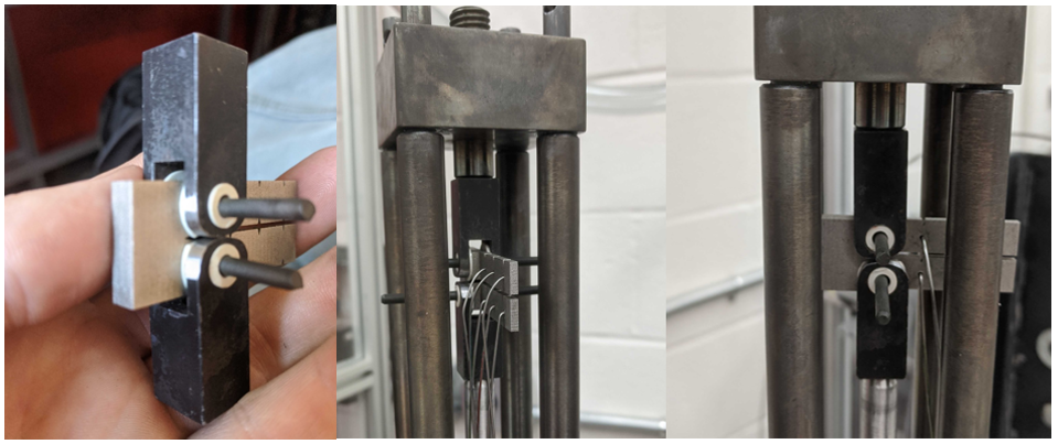
FLiNaK is stored in its frozen state in the lower chamber of the autoclave while not in use. Test specimens are positioned between a clevis and a load-bearing tube. The tube has three heat shield fins to better insulate the salt with feedthroughs to accommodate wiring from additional instrumentation. Thermocouple probes are fed into the body of the MSLF to monitor lower chamber temperature. The lid has multiple feedthroughs that are used for upper chamber thermocouples and additional feedthroughs for future instrumentation. The servo can be actuated in load, strain, or stroke-controlled modes, giving flexibility to the type of testing that can be performed. The same software can be configured with DCPD instrumentation to measure and record crack length and stress intensity factor in operando for K-controlled fatigue crack growth rate testing.
Extensive measures have been taken to minimize personnel exposure to HF gas, which can be created through a hydrolysis reaction between the moisture and impurity fluorides if the salt is not properly baked out before melting. The Ar cover gas effluent, including any salt or acidic vapors, is sparged through two HDPE carboys containing a 1M NaOH solution, after which it flows through a steel wool trap to react any residual acids before being released to the building exhaust stack.
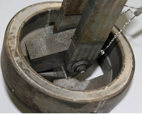
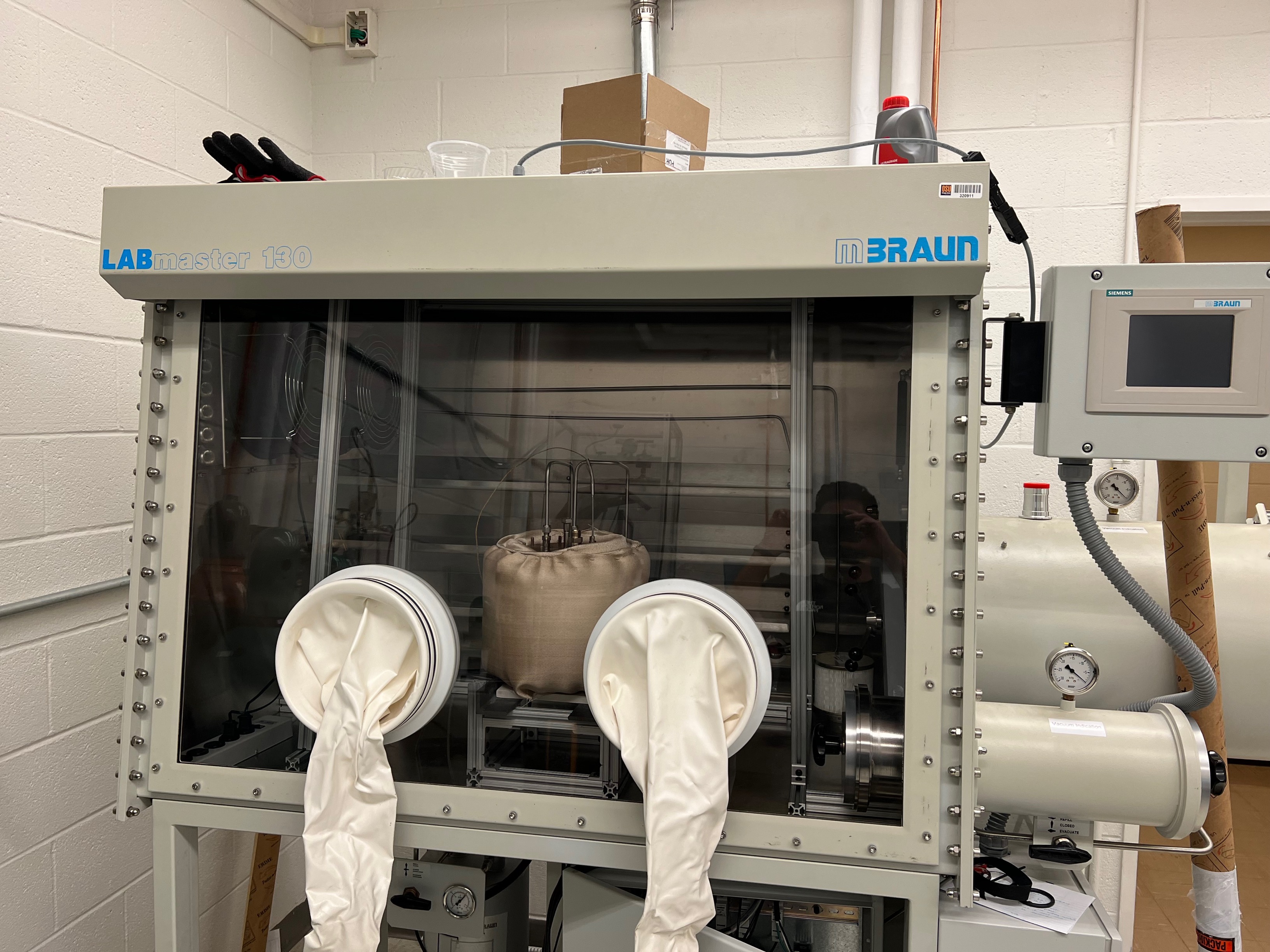
The Salt Prototyping and Development Environment (SPaDE) is a simple static molten salt crucible test facility contained within an inert atmosphere glovebox. It is primarily used for static corrosion coupon testing of material samples in addition to studies of salt chemistry and chemical monitoring. It is comprised of a stainless steel outer crucible with either an alumina or graphite internal crucible, for testing in chloride- and fluoride-based salts, respectively. The crucible is designed to meet the needs of a wide variety of experiments through the use of various exchangable lids, allowing for installation of different types of instrumentation or custom experimental apparatuses.
The facility is capable of pushing temperatures of up to 800°C to enable the melting and mixing of eutectic salts from pure constituent components. The crucible itself also has a dedicated inert cover gas feed and exhaust to mitigate the release of acid or salt vapors into the glovebox volume and to neutralize these vapors prior to discharging to the building exhaust. The glovebox temperature is also controlled via a water-cooled heat exchanger mounted internal to the glovebox volume. Facility control is automated via the use of a LabVIEW-based control scheme.
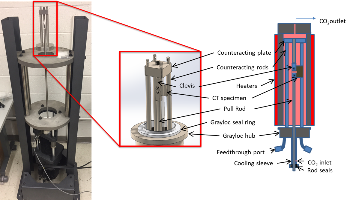
The Gaseous Load Frame and Autoclave (GLFA) mates an Interactive Instruments electronically-actuated load frame to a sealed vessel designed for temperatures of up to 650C at pressures of 20 MPa, enabling testing in environments relevant to supercritical carbon dioxide (s-CO2) Brayton cycle applications, in addition to environments relevant to high-temperature gas reactor designs. Several feedthroughs in the vessel allow for both thermocouple and direct current potential drop instrumentation for fracture mechanics-based crack growth testing in these environments.
Preliminary testing of CT specimens instrumented with DCPD has been performed in the GLFA. Future work includes adding the instrumentation enabling controlled addition of impurities to the gaseous inlet stream in addition to adding capabilities for compositional analysis of the effluent gas.
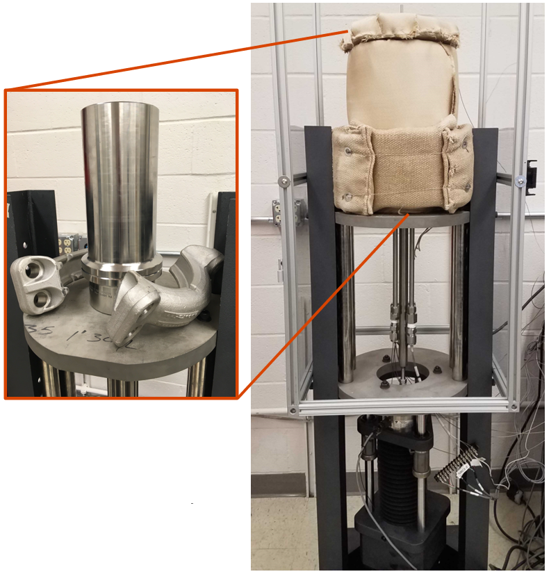
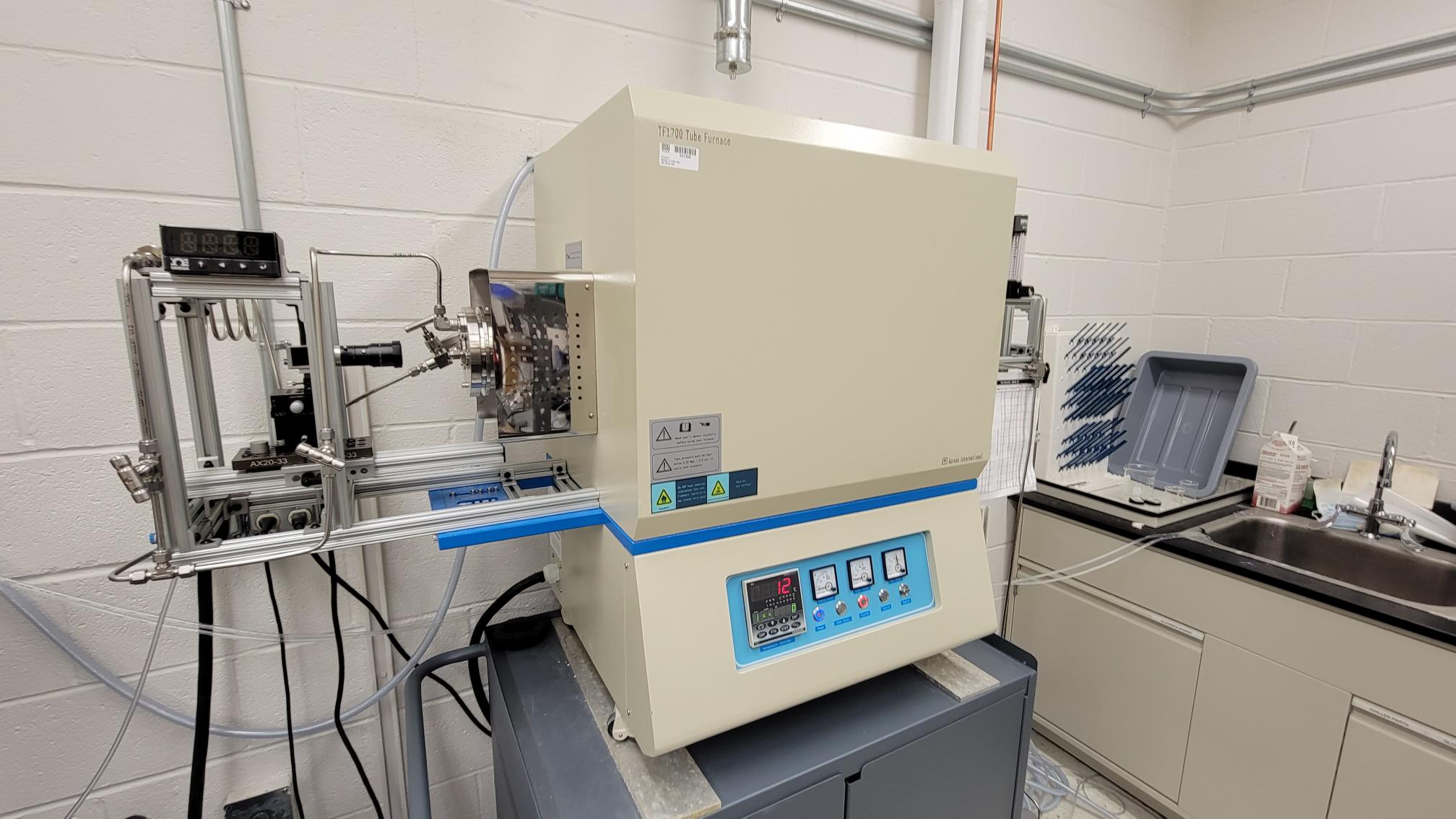
The A-134 laboratory features a modified high-temperature tube furnace, enabling both long-term annealing experiments and sessile drop testing at temperatures of up to 1700 °C. The furnace is an Across International TF1700 that is equipped with vacuum sealing windowed flanges and gas feed lines to enable testing in air, vacuum, inert gases, or other gaseous environments of interest. One of these flanges supports an internal Mo tube feedthrough with an attached yttria nozzle for metal droplet extrusion. Imaging hardware, including a CCD detector and collimer beam source, is attached externally on goniometric stages for recording inside the furnace volume.
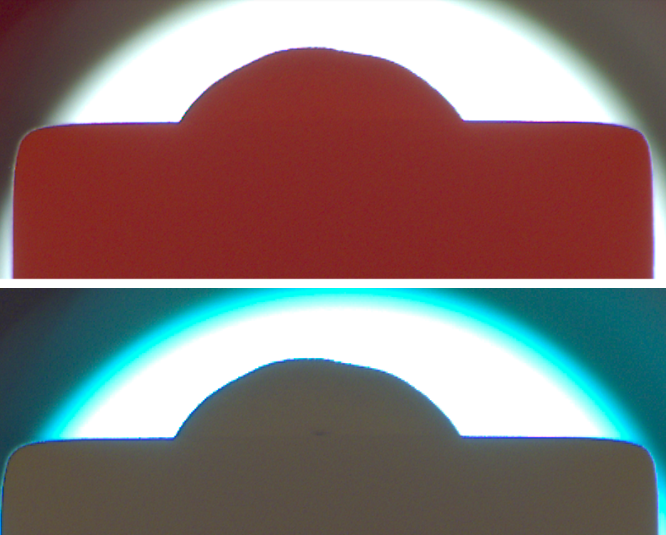
High-temperature metallic sessile drop testing represents a unique capability within the Nuclear Materials Degradation Research Group. In these tests, solid metal is loaded into the nozzle and the furnace is sealed and purged. The furnace is brought up to temperature, usually under an inert argon atmosphere, to melt the metal while avoiding oxidation. A positive pressure is then applied to the Mo tube to extrude a metal droplet onto the substrate. Once the droplet is created, an orthographic image is captured from which the contact angle can be measured. Imaging can continue over a long-duration test to capture how wetting behavior changes over time due to chemical interaction. After the conclusion of the test, the surface of the substrate can then be analyzed using analytical techniques such as scanning electron microscopy or x-ray diffraction to determine the extent of surface interactions at the point of contact.

